Saturday 30 November 2013

Battery compartment and some bits for IVA

The main cables were run into the battery compartment but still needed cut to length and connected up. I had ordered a 200 Amp Relay which got delayed a bit but now that its arrived it was as good a time as any to get that compartment finished.
Once the isolation relay was mounted and the trigger wire ran inside the car, the heavy duty cables were all connected up. The trigger wire is a ground connection so power to the other side of the coil was just taken from the main battery feed with a small inline fuse. 
A rubber cover was also put over the positive battery terminal, think I read somewhere its required for the IVA.


On the IVA note, some time was spent in the foot wells today making sure all bolts had caps or were button heads, foam on the bottom edges of the wiper motor and along the back edge of the alloy infill panel under the dash. The windscreen pillar posts had alloy covers but added rubber edging around the covers. On the drivers side the pedals got some abrasive material for grip.


Ran a wee bit of rubber around the door finisher as just just encase.


Friday 29 November 2013

Steering Column finishing

Spent ages sorting and getting the steering column finally fitted, liking the look of it and had to fit the Moto Lita wheel to see how it all looked. Just a pity the Vectra one has to be fitted for the IVA test.
Liking the look of the GD stalks when its all put together.
The dash switches got the decals applied today as well, Fog light, light and heater fan plus the hazard warning light symbol.


Pic below is wheel just on the splines but not bolted right down.


Now with the not so cool IVA steering wheel :(


Next on the to do list is to sort out some IVA issues in the interior before bolting the seats in.


Thursday 28 November 2013

Engine bay

I went to fit the steering column the other day but realized I needed to tidy up that corner of the engine bay and also make a bracket so the braided hoses meet the IVA clipping requirement.
The bracket was simple just a piece of 25mm stainless bar cut to length then drilled for the steering column U clamp and another 6.5mm hole for the stainless P clip.


Bracket sorted and the rear corner dressed, The Carbon cover I made was put on where the big grommet was in the bulkhead to allow all the main cables and ecu cables etc to run into the dash and was dressed of with some rubber U channel. Above the cover I added one of the GD badges I had in the parts cupboard :) All in all another few time consuming jobs out of the way and its starting to look good. 


Wednesday 27 November 2013

Brakes and side vents.

Carried on with the drivers side side vent today and it was pretty straight forward apart from the one bolt that goes into the footwell, I needed the second pair of hands to get it installed. I also finished of the passenger side by adding some 20mm electrical grommets to the heater air holes. Thats now one job less to do when it comes round to the IVA checklist.
We took into bleeding the brake and clutch systems which didnt go according to plan and in typical fashion its always the most aquard nuts to get at that cause issues. The bridging pipe on one of the calipers had a leak on the very inside, after a bit of time flaffing about A spanner was cut and modified to get at the offending nut, fingers crossed it now seems fine, On hindsight it may of been a good idea to put the brake and clutch system under pressure before the body goes on.
Both the Brake and clutch systems seem to be fine now but with a fresh head I'll check them again.
The next  visit to the workshop will be for a good tidy up as it looks a right mess tonight :)

Brake/ Compartment and side vent

I had added some gel coat to the car in the engine bay where there were a couple of holes that were not being used and also a couple of small repairs on the outer body so in the mean time it was on with a few other wee jobs.
The brake clutch compartment just needed the reservoirs finished and its now ready for the DOT4 to be added to both systems.


The long stainless M3 button head bolts and nuts arrived, so that is another job progressing at the moment, I cut some spacers for the back of the temporary infill panels that I had made so they would fit flush with the body. On the passenger side 20mm holes were drilled to allow air into the heater box. 
I just need to fit some 20mm grommets to the holes and get the drivers side one completed.


Monday 25 November 2013

Body work

Took a notion today to give the body a bit of a clean, after all it was near 2 years from it had a decent clean /buff. I knew about a couple of the gel repairs that i had to do but forgot the smaller ones which take up just as much time. I came across these as I give the shell a quick wash down and decided to give the body a quick Farcela G10 clean up.
On the exterior most of these repairs or pin holes are now sorted but still have a few to do in the engine bay where there were holes that I no longer need due to moving things about to keep a very clean look in the engine bay or as clean as I can given that its a modern engine which a shed load of wires feeding the ECU.


 The shell is now looking a bit better again, no doubt it will get dirtier before the build is complete :)

in no particular order the next job to get started was the wire mesh for the scoop where the oil cooler would live. I still had the piece that was cut out for some reason but this proved handy as a former for shaping the first piece of stainless mesh. Once the mesh was cut and shaped the mesh was set into place and the piece of fiberglass that was used  as the former was put behind the mesh before the G clamp with VERY little pressure and a block of wood clamped it at one side. Another clamp and a piece of flat plastic was used to do the same with the other side.
The next step hopefully tomorrow evening will be to use a polyurethane sealant and bond the mesh in place.

Sunday 24 November 2013

Control stalks

The steering column area got a wee bit done on it today as well, the stainless cover I have for the front face of the steering column has symbols engraved on it so Andy said the stainless stalks could be fitted before the IVA test. First was to run the hacksaw through the plastic stalk just before the flange where the rubber boot sits over.


In the picture above you can see the exact place the stalk is cut and filled. Once thats done a small pilot hole was drilled in the center of the shaft then a 5mm drill used to drill down the stalk. The length that the stalk is drilled is the amount that your GD stainless stalks are threaded.


Once drilled and tapped with a M6 x 1.0mm tap the stainless stalk is then screwed in. I applied some thread luck or nut retainer medium grade when doing this.


Dash

I got pulled away from the car for most of this week as work just went mental and was working all hours over the past 5 days to get on top of things so I could get back to the important job again :)
The build is coming along nicely now and getting to the stage where I need to really forward plan on small silly bits or jobs just cant be completed.
With all the wiring in the dash area out of the way for the IVA it was time to start getting the dash mounted, unlike the leather covered dash the carbon dash has to have bolts secured to the back of the dash as bolting though the dash would look a tad naff even with button heads.
Some strips of stainless was cut for the 4 mounting bolts and then drilled with a 6.5mm hole in the center, the bolts were then put through the flat strips and welded.


Pic is a bit poor but shows the job, Next was to mix up some fiberfill repair paste and put a blob on the back of the dash. The mounting bolt was then pushed onto it and more paste added to cover the securing bolt. One thing for sure it isnt going to vibrate off.

Once the bolts had set a corresponding hole was then marked and drilled in the body. I used some marked paint on the ends of the bolts to mark the dash and drilled the holes. As the dash is presented at an angle due to the bottom lip of the dash the dremmel was then used to elongate the holes down slightly to get the dash to fit snugly into place.


Dash fitting now though the bottom alloy plates have to be sorted to fit properly yet.


Tuesday 19 November 2013

Tacho settings

I had noticed the Rev Counter was reading very low ie 200 RPM and after a while it became apparent that the dip switch settings on the rear of the Tacho were not set right for my LS6 engine ( same for LS1). The ECU I'm using is a Delphi which is the original GM unit.
IT took a while with a few of the Chaps on the Cobra forum chipping in before we got the correct settings.


In the above picture you can see the dip switch which is behind the rubber grommet normally.
The correct settling is as follows  1 off  2 off  3 on  4off.

Settings for Smiths Rev counter link here.  new type

older type here  both supplied  by Alan :)

Happy Jim's Technical info on it
The number of crankshaft medium resolution pulses (24x pulses) to hold the tacho output high (should match {G1205} "Tacho Pulses Low").

The number of output pulses P is calculated as P=24/(N*2) where N is the value of this calibration.

Sample values for this calibration:
For 12 pulses, use N= 1
For 6 pulses, use N= 2
For 4 pulses, use N= 3
For 3 pulses, use N= 4
For 2 pulses, use N= 6
For 1 pulse, use N=12


 answer = output is 2 pulses per Rev.        ..................Switch 1 off Switch 2 off

Switch 3  in the on position...... as it appears the ECU needs a resistive load to 12v, turning on switch 3 achieves this.

Switch 4 is for calibration only hence stays in the off position.


Mac Stowt uses the above settings on his LS2 engine setup as well.


Another wee snag sorted with the help of the Cobra club lads :)


Number plate bar


The Number plate bar needed fitted and its a tad aquard on your own, one of those jobs where you need the 3rd hand to hold something till you get it marked. I also cut a piece of plywood the size of the number plate but have not got around to getting it clamped onto the bar yet. The wood is only installed temporarily  BUT still needs to have a smooth radius on it for the IVA so I ran around the wood with the router.


Sunday 17 November 2013

Battery support and steering column dressing

Came out to the workshop this morning all ready to rumble but one look and I remembered it was time to have a good tidy up and get everything back to where it should be, that took care of 2 hours.
The GD Battery compartment is quite tight to get a good sized battery in and with the opening the battery needs to be twisted at an angle to enter and then turn broadside, not the easiest thing to do under a wheel arch with a lead acid battery. To make sure I could get the biggest battery in that would fit I made up a raised support which allowed a slightly bigger battery.
The battery I'm using is a Solite 630 CCA with a 70AH capacity measures 260mmx175mm and has a height of 200mm.
When the support was installed I laid some rubber on top between it and the battery.


The other job I tacked today was the steering column shroud and covering it with leather the same as the interior and also fitting the stainless steel front which GD had made.
No point in a step by step guide to doing this as I done it from Simon's post on his blog which gives a step by step guide.  CLICKY

I'm not sure whether I can fit the GD stalks I had made now or if I need to wait to after the IVA ,I'll check this one out with Andy before fitting them.


Not sure whats next on my list to do, one thing for sure its not a short list but I'll make that decision after some sleep :)

Saturday 16 November 2013

Fog light, handbrake switch and brake compartment light.

All the wee jobs take loads of time up and what you think will take an hour normally takes 3 hours by the time you decide what way to do it and get started.
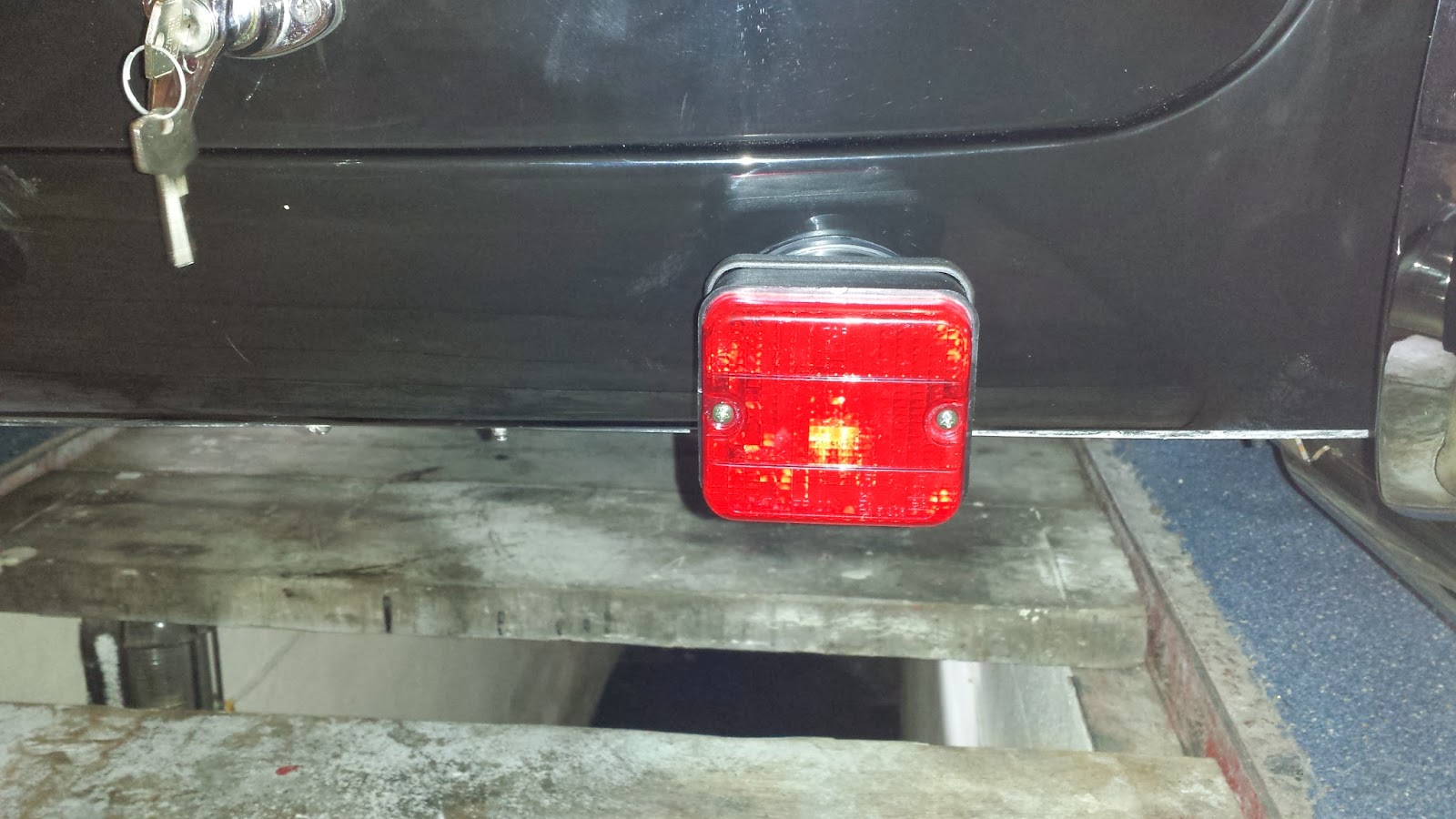
I removed the GD rear fog light I had put on earlier for a not so cool looking IVA square E marked light which mean modifying the new light a bit and lifting part of the boot carpets which had been glued in.
That's one less job to do off the IVA list when it comes round to that time.


The led lights I ordered of evil bay arrived and I installed one in the Brake / clutch compartment which took a few hours flaffing about and getting tings tidy. I angled the light so it put plenty of light around the washer bottle as well.


Great wee light and £6.59 for 2, but with no seals I would not like to try them on the outside of a car as that is what they are listed for, day running lights :D

I'm using a Jag fly off handbrake and whether the brake is on or off the handle is down so I wanted a warning switch added to the handbrake, this took a wee bit of work as I had to come up with a bracket to get the switch arm working in the right position.


My handbrake cable is the right length and the right end for the handbrake side of things but its a tad to long and has the wrong end on it for my Jag calipers so after working it work I sent of an email to speedy cables today and hopefully they can shorten it and put the correct end on the cable and let me get the handbrake finished.


Thursday 14 November 2013

It's alive

Its that time and with all the Engine and ECU wiring done it was time to empty in a Jerry can of fuel into the tank and fill the system with coolant.
I hooked up a battery we had here in one of the classic cars and put the battery charger on start mode.....................................................................  With a rather nervous turn of the ignition the start button was gingerly pushed and she started to crank over the fuel pump had already kicked into life with the turn of the ignition key, The engine after a couple of turns made an attempt to start but I could smell petrol so had a look around the fuel system and we had a leak at the blanked side of the regulator.
A wee while later and fixed it was back to starting up the engine again and it burst into life......... man thats a good feeling.
The engine was run up to temperature and everything was fine apart from a slight leak at the manifold gasket which proved to be a very time consuming snag to fix on the manifolds.
After talking to Andy at GD, the engine was run again with the Radiator cap of to watch for the thermostat opening and the flow through the expansion tank. It is not long after the stat opens that the 1st fan should kick in and its a very good way of gauging the temperature of the engine as the Smiths gauges are only approx.
As the stat opens gradually the flow is slow at the start then it goes into full flow.
No other problems found apart from one of the fans needing connections changed to pull instead of pushing the air flow.
Added a wee video of the engine now. and very happy that the car is at this stage so time permitting its full steam ahead for the next couple of days and get a few other jobs of the very long list that is still to be done.


Engine start up Video


Wednesday 13 November 2013

Wiring , yup more wiring.

Went on a visit to the scrap yard today on the quest to get a OB2 data socket and after standing in a que for 30 mins I got sent out the back with a high vis vest to obtain the elusive socket to which the guys hadn't a clue as to what it was.
This evening with much help from  Happy Jim  I was able to sort out the MIL lamp trigger wire and also work out the fan 1 and fan 2 triggers on the LS6 ECU same as LS1,. Next was to confirm the wiring and check out the OB2 data wire.  The OB2 data socket still needs sorted and hooked up into the car and the MIL lamp ordered and wired.
I also opted to put a master over ride switch on one of the fan circuits just encase it was ever needed. while doing that I tested out the rest of the fan circuits by applying a ground to the coil on the relay circuits to see what way the fans were going, ie push or pull............ Yup one was wrong so wiring changed but hmmmmmm this didnt make much difference and another look at the fans showed the blades on on fan to be the wrong way round. This took a good hour to sort but both fans are working now the way they should once the ground trigger is applied across the relay.
Enough for today and time to get the beast running ...................................................................

Tuesday 12 November 2013

More wiring and POWER

Well there comes a time when you just have to apply some sort of power to the beast..................
So it didn't get to complex and a load of snags to fix in one go i decided to leave the engine ECU out of the equation for the moment meaning that all the auxiliary circuits were connected bar the few jobs that I had remaining to do on the wiring.
On power up not a lot seemed to happen apart from the brake lamp test switch working, hmmmmmmm first thoughts were a bad earth but everything was fine,,,,,,,,,,,,,,,,,, Now the funny part. It really does help when testing the electrics if you take the fuse box cover off and insert fuses :D.
With the fuses in place and a sigh of relief the testing began , first fault was the brake lights not working which turned out to be a faulty brake switch at the pedal box and it was a brand new one at that. With that replaced the brake lights were spot on.
Next fault was the air horns they needed the connections swopped to blow air instead of pulling it through the trumpets. The last fault ,,,,,,, well not a fault,,,,,,, the fog light wouldn't work. All i will say at this point is make sure you turn on your lights before attempting to turn on the fog light :D ,,,,,,,,, Fog light works fine.

With that end of the wiring out of the way the next job was to supply the engine with 6 liters of 5/30 Castrol oil and fill the system with coolant. :)

Next job in hand will be hooking up the ECU fuses and a Jerry can of fuel to see what happens, my stomach is churning already :)

Monday 11 November 2013

More wiring and a few odds and ends

A long day today, punched in 12hrs at the car and really started to get on top of the wiring and back up to speed with it.  The heated seat wiring is now complete apart from waiting on the switches to arrive and a bezel to be made to house them. The permanent 12V for the ECU has been sorted and fused, also the main power for the ECU has been added through a Relay which is triggered via the second Ignition key position. A few other wires put in and cables shortened and tidied.
The battery compartment got a lick of paint and the brake and master cylinder compartment. I had decided when working in these that some paint would brighten them up and whilst looking for something else I came across some Green hammerite that had been kicking about the house for over a decade so it was about time it was put to good use.

Still some work to do in there, finish the brake reservoir and connect the wiring, I,m also waiting on LED lights arriving for this compartment and also the battery compartment so inspection will be easier when the car is on the road.
Another job on the drivers side was to secure the headlight better, I just didn't like the idea of self tappers holding the light in place. As with the passenger side I secured the light with 5 mm stainless bolts and lock nuts.

Just need to apply some Waxoyl around the bolts now and that's another job out of the book.

I had trail fitted the dash when  trimming it to fit correctly but found poping the trim in behind it a tad aquard for fitment so I cut and measured the trim and glued it into place on the dash with the view it would be easier to fit the dash with it in place.


Roll on tmw for another good day at the Cobra :)

Sunday 10 November 2013

Well another day another Dollar or something like that the saying goes but its a Cobra build so the saying should be another day another few GDP spent on  ebay and the net on nick knacks plus a trip to B&Q for another tin of impact adhesive :)
No pics today as it was just wiring and if you decide like many have done to modify wiring ie hide wires or add wiring for heated seats etc, time just becomes a big sponge. Today I modified the heater wiring and got it connected up thanks to

 the Diagram from Denis is spot on and so easy to see the whole wiring for the heater from start to finish, He has done this for the different sections of the GD Cobra loom, Thanks :)

With the heater out of the road I then took into the wiring and conduit work for the heated seats which meant re gluing some of the carpet hence the visit to B&Q. The wiring is all done and dusted now up to the dash area I'll have to wait for some IVA type switches arriving to finish of the wiring.
IF and thats always the big question, all goes Cobra wise and life in general I'm hoping to have the wiring mainly sorted this week and some power applied to the car APART from the ECU so I can test the wiring and once thats all sorted well hmmmm the scary bit but the exciting bit we all look forward to 3,2,1   we have ignition :D

Saturday 9 November 2013

Been a long time from I have got near the build so needless to say a long way behind on things. I spent about 2 days trying to figure out exactly where I had left off which just happened to be in the middle of the wiring.
Glad I made notes but finding the file was another time consuming issue :)
I started on the wiper motor and got it wired up, It will need tested later when the power is put to the car for the park position.
Next was the washer bottle which had been a pain in my side for a long time not knowing where  to install it. Being plastic it didn't float my boat to say the least having it in the engine bay.
After a bit of head scratching I decided to put it in the drivers side compartment where the clutch and brake master cylinder lives. In doing this I had to modify the wiring loom a bit.
Once in place and wired I then made the decision just to fit one twin washer jet after talking to a few on the forum etc. The Jet is positioned 20mm back from the edge of the lip nearest the bonnet and 41mm from the screen rubber. This allows fitting room for the nut at the bulkhead inside.


With the washer bottle now living in the compartment with the clutch and brake master cylinders I then decided to also put the fluid reservoirs for these in the compartment as well rather than the engine bay, this was down to both reservoirs again being plastic and I could not source nice stainless steel ones on the net anywhere. I then modified the brake level sensor wiring so it would end up in the compartment.
As the compartment is dark I have ordered  an LED light which I will install when it arrives which should provide good lighting for inspecting the fluid level of the 3 containers. I ran a couple of wires in for this light also.


The only down side to this moving was that I already had the 6 holes drilled in the engine bay before the body went on for all the reservoir tubes so on the outside I had to make up a stainless steel plate to cover the holes not in use.